
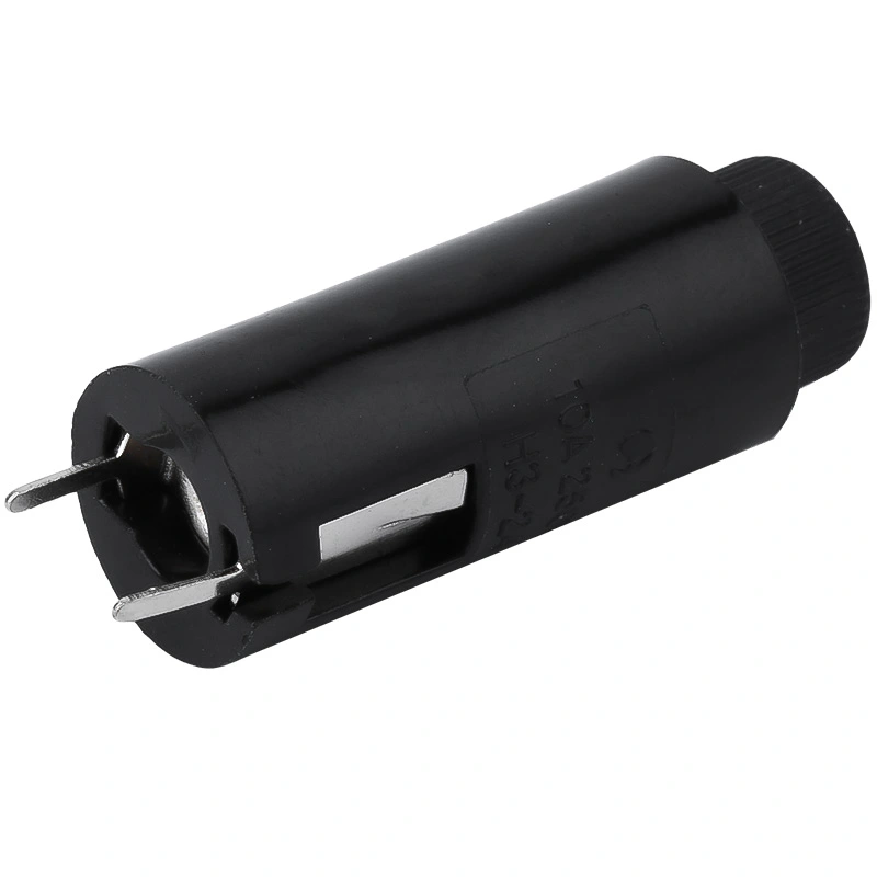
On a low-voltage control board, the placement of a PCB mount fuse holder is mostly a question of convenience: put it near the power input, keep the traces short, done. On a board that carries mains or high-voltage DC, placement becomes a safety decision, and the distance between two pieces of copper matters more than the routing elegance. This article covers the two distances that govern that decision, how to determine what your board actually requires, and the layout techniques that let you meet the requirement without doubling the board size.
Creepage and Clearance Are Not the Same Thing
These two terms get used interchangeably and they are not interchangeable. Clearance is the shortest distance through air between two conductive parts. It is governed by the breakdown strength of air and by altitude — air is a better insulator at sea level than it is at two thousand metres. Creepage is the shortest distance along the surface of the insulation between two conductive parts. It is governed by surface contamination: dust, flux residue, moisture, and the conductive paths that form when those combine. Creepage is almost always the binding constraint on a real board, because the surface of an FR4 substrate is a far worse insulator than the air above it. A board that passes a clearance check can still fail on creepage if there is a direct unbroken path across the laminate between two contacts.
Why the Area Around the Holder Is the Critical Zone
The holder is where several unfavourable conditions meet at one point on the board. On one side is the incoming supply, at full line or bus potential. On the other, millimetres away, is the protected circuit — and in many designs, a low-voltage secondary side with a completely different insulation requirement. Between them are two metal terminals, a soldered joint at each, and often a fuse body that can be removed and replaced by a user. Add heat. A protective device carrying current near its rating runs warm, and warm surfaces attract less condensation but accelerate the ageing of the surrounding laminate and any residue on it. Add serviceability. A holder, unlike a fixed component, is a place where someone will eventually insert a tool or a replacement part, potentially disturbing nearby components or leaving debris on the board. For all those reasons, the area around the holder is where insulation coordination is most likely to be inadequate, and it is worth treating as a defined keep-out zone rather than whatever space is left over.
What Determines the Required Distance
The required creepage depends on four things, and you need all four before you can pick a number:
- Working voltage, including any transient or surge the design must withstand — not just the nominal value
- Pollution degree, which describes the environment the board operates in: a sealed consumer enclosure is cleaner than an industrial panel with unfiltered air
- Material group of the substrate, usually expressed as the comparative tracking index of the laminate
- The insulation type required between the two circuits — functional, basic, supplementary, or reinforced
Standards publish tables combining these into minimum distances. Use the applicable standard for your product category and market rather than a generic figure, because the numbers differ materially between them, and reinforced insulation requirements are substantially larger than basic ones. One practical caution: many designers read the table for the nominal voltage and stop. If your product has a defined surge or transient requirement, check whether the standard expects you to use the transient voltage instead.
Slots, Grooves, and Barriers
When the straight-line creepage does not fit, you do not necessarily need more board area. You need a longer path, and there are legitimate ways to create one. A slot milled through the board between two conductors forces the creepage path to follow the slot edge rather than crossing directly. To count, the slot has to be wide enough and long enough that the path around it is genuinely longer, and standards specify minimum slot widths for this reason. A cosmetic 0.5 mm groove does not achieve anything. An insulating barrier placed between the two conductors, bonded to the board, can also extend the path vertically — the creepage now has to go up one face, across the top, and down the other. Barriers must be of suitable material and properly fixed. Both techniques need to be verified against the standard rather than assumed. And both create assembly considerations: slots collect flux and debris, and barriers need placement clearance in the pick-and-place programme.
Conformal Coating and What It Does Not Do
Conformal coating is often proposed as a way to reduce creepage requirements, and this is where boards get into trouble at certification. Coating does help against contamination and humidity. It seals the surface, keeps flux residue from becoming conductive, and reduces the effect of condensation. That is a real reliability benefit. What coating generally does not do, on its own, is let you reduce a creepage distance, unless the coating system has been qualified for that purpose under the relevant standard. Coatings crack, delaminate, and wear at edges — exactly where a creepage path matters most. Treating coating as a substitute for distance is a common and expensive mistake. Use coating for reliability. Use distance and, where necessary, slots or barriers for insulation.
Heat and Soldering Considerations
Placement is not only about insulation. A device carrying significant current dissipates heat into the pad and the surrounding copper. Give it enough copper area to spread that heat, keep it away from temperature-sensitive parts such as electrolytics, and avoid placing it directly under a component that will trap heat above it. Soldering matters too. Wave soldering exposes the holder to thermal shock, and repeated reflow cycles can deform a plastic body or relax a contact spring before the product ever ships. Confirm the holder is rated for the assembly process you use, and check the profile at the holder location rather than trusting the average board temperature. For hand assembly or service replacement, leave enough clearance around the body for a tool, and consider whether the device should be removable without disturbing anything else.
A Layout Checklist
Before releasing the board, confirm:
- Working voltage including transients, and the applicable standard's table values
- Pollution degree and material group assumed in the calculation
- Insulation type required between the circuits on either side of the holder
- Achieved creepage measured along the real surface path, not point to point in a straight line
- Achieved clearance, with any altitude correction applied
- Slots or barriers, if used, meeting the minimum dimensions in the standard
- Copper area and thermal relief adequate for the rated current
- Soldering process compatibility and clearance for assembly or service tools
- Silkscreen marking identifying the rating, so the field replacement is correct
Summary
Creepage, not clearance, is usually the constraint, and it is a surface problem rather than an air problem. Establish the working voltage including transients, the pollution degree, the material group, and the insulation type, then lay out to the resulting distance — using slots or barriers to lengthen the path if space is tight, and treating conformal coating as a reliability measure rather than a way to reduce distance.
About Our PCB Holder Range
GFEFUSE is the brand of Dongguan Gongfu Electronics Co., Ltd., an electronic protection device manufacturer founded in Dongguan, Guangdong in 2013. Our integrated development, production, and sales team operates five advanced production lines with thirteen R&D engineers, and our products are exported to customers overseas. Our PCB fuse holder clip range covers horizontal and vertical mounting for through-hole assembly, with body materials rated for standard reflow and wave soldering profiles. These are supported by our wider fuse holder range for panel and inline applications, by fuse accessories including covers and insulating parts, and by our high voltage fuse portfolio where the board interfaces with higher voltage DC. Products carry UL, cULus, TUV, CE, and CQC certification and comply with RoHS and REACH directives, serving consumer electronics, automotive electronics, power equipment, communication systems, and new energy.
Conclusion
Placing a PCB mount fuse holder well is mostly a matter of knowing which distance you are designing to and measuring it along the path that actually exists. Do that, provide the copper for the heat, confirm the soldering process, and mark the rating on the silkscreen. The board will pass its insulation testing the first time and the device will still be serviceable years later.
Send us your working voltage, pollution degree, board material, and mounting style. We will confirm the right holder and the creepage guidance for your layout.
Frequently Asked Questions
Answers on placing board mount holders safely.
What is the difference between creepage and clearance?
Clearance is the shortest distance through air between conductors and is governed by air breakdown and altitude. Creepage is the shortest distance along the insulating surface and is governed by contamination. On real boards creepage is usually the binding constraint.
How much creepage do I need around a PCB mount fuse holder?
It depends on working voltage including transients, pollution degree, the comparative tracking index of your laminate, and the insulation type required. Read the values from the standard applicable to your product and market rather than using a generic number.
Can a slot in the board reduce the required distance?
It does not reduce the requirement, but it lengthens the available path, which can let you meet the requirement in less space. The slot must meet the minimum width specified by the standard, and the path must be measured around the slot.
Does conformal coating let me use a smaller creepage distance?
Generally no, unless the coating system has been qualified for that purpose under the relevant standard. Coatings crack and delaminate at edges. Use coating for reliability against contamination and keep the distance you calculated.
Do I need to worry about soldering heat?
Yes. Wave soldering and repeated reflow can deform a plastic body or relax a contact spring before the product ships. Confirm the holder is rated for your assembly process and check the profile at the holder location.